Parallel Circuits
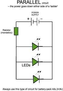
The diagram represents a parallel circuit. If we think of it as a ladder, the power flows down either side of the ladder and the load (in our case LEDs) are the rungs.
This means that each LED gets the same current. The resistor sets the current level for each individual LED.
This type of circuit is mainly used when the supply voltage is low, for instance in our 'AA' battery kits.
Parallel circuits are only viable when all the LEDs used are of the same (or very similar) characteristics. They can only be guaranteed to work properly if you use the same colour LEDs.
Also note that the resistor is more likely to overheat in this arrangement than a series circuit - it has to deal with (in the above case) 3 times as much power as it would if the circuit only had one LED. This is not a problem in small arrays with a few LEDs, but once you get above 6 or 8, make sure you test the resistor for heat before building it into something flammable. This problem can be largely avoided by using a resistor with a larger watts (power) rating.
If you want to learn how to calculate resistance values for LED circuits go here.