Use an LM317 as a Voltage Regulator
 As usual when it gets a bit advanced I urge extreme caution and remind you that you are on your own - this knowledge is offered with no guarantees or promises of safety or usefulness (...our disclaimer, that is).
I have made the information as simple as possible.
If you want to be totally sure of the facts, have a look at a manufacturer's data sheet - you could download this one here.
There is plenty of advice out there on the 'net. You will be able to confirm what is here, and maybe find out more too - then let us know.
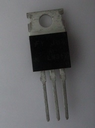
This type of LM317 (there are a few different configurations, but they all do the same thing) appears to be a metal backing plate with a hole in it. Mounted on the plate is a black, plasticy box with three electrodes emerging from it. Obviously, the magic happens inside the little box, which, among other things, contains 29 transistors. The whole thing is about 3cm long.
The LM317 can handle an input voltage of up to 40v.
It uses 3v itself, so can provide up to 37v.
Pin 1 is on the left and is referred to as 'adjacent'. Pin 2 is in the middle and is referred to as 'out'. Pin 3 is to the right and is 'in'.
Here's a simplified diagram to show how to wire the LM317 to get it to act as a voltage regulator.
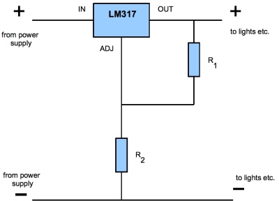
The resistors R1 and R2 are being used to control the voltage.
R1 should be 150Ω or higher.
The output Voltage, Vout = |
1.25 x (1 + R2)
R1
|
.. which re-arranges to give us ................. R2 = |
R1 (Vout - 1)
1.25
|
We need to chose R1 (>150Ω) so say 200Ω
In this example let's say we are wanting a 6v output. The input is irrelevant for the purposes of the calculation, just make sure its not more than 40v.
So now, R2 = |
200 (6 - 1)
1.25
|
= 760Ω |
You'll need to mess about with resistor values to get the correct ratio, then probably settle for something that's 'close enough'.
However, if you were to get a 0 - 1000Ω variable resistor and you already have a volt/multi meter, you could simply adjust R2 until you got your desired output.
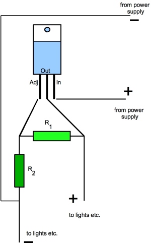
If you are still with me by this stage, you probably need a break... but before you go, here's the same circuit diagram made a little more understandable...
When you have your device running, test that none of the parts are getting too hot (including your power source). Test the voltage that is coming out before connecting your load - if you get the calculation wrong the voltage will be wrong too.
Remember it can only supply a maximum of 3v less than the input voltage.
Using an LM317 as a Current Regulator is a degree or two less complicated...